
In the previous DIY article, DIY: USB2S Programmable USB-to-Serial Adapter Guide, we covered the detailed interfaces and functions of the programmable USB-to-serial adapter development board. In this article, we will continue by explaining how to configure and modify the parameters of the programmable USB-to-serial adapter development board. If you're interested, keep reading!
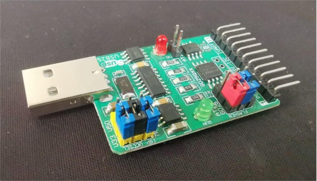
Parameter Settings
1. UART Communication Parameter Settings
The default UART1 and UART2 communication parameters are 9600, N, 8, 1. These can be modified using the following command format: [STU1] B N D S
· B: Baud rate (bps), can be any value between 1200 and 921600
· N: Parity bit, where N = None, A = Odd parity, E = Even parity
· D: Data bits, can be 8 or 9
· S: Stop bits, can be 1 or 2
For example, to set UART1 communication parameters to 9600, N, 8, 1, send: [STU1]9600 N 8 1
Note: Apart from the baud rate, the other three parameters default to N81 and cannot currently be changed.
Note: After executing this command, the registers BAUD_U1 and BAUD_U2 will be updated synchronously but not saved permanently.
Note: When modifying one UART interface, the other UART interface will be changed simultaneously, so both UARTs always share the same communication parameters.
2. I2C Communication Parameter Settings
The default I2C communication parameters are 52, MSB. You can modify them using the command: [STIIC] B xSB
· B: Communication speed code, ranging from 0 to 63. The corresponding speeds are listed in the table below.
· xSB: Data transfer order, where MSB means Most Significant Bit first, and LSB means Least Significant Bit first.
Note: After executing this command, the registers BAUD_IIC and ISCW_XSB are updated synchronously but not saved.
Note: The system clock divider affects both I2C and SPI communication speeds.
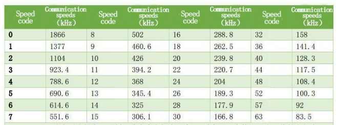
Note: The I2C communication speed is limited by the pull-up resistor. The table below reflects measurements taken with a 2kΩ pull-up resistor. Using a smaller resistor will increase the actual communication speed, and vice versa.
The following tables show I2C speed codes and actual measured speeds for different clock dividers (4, 8, and 1), as well as SPI speeds:
· IIC speed codes and measured speeds at clock divider 4
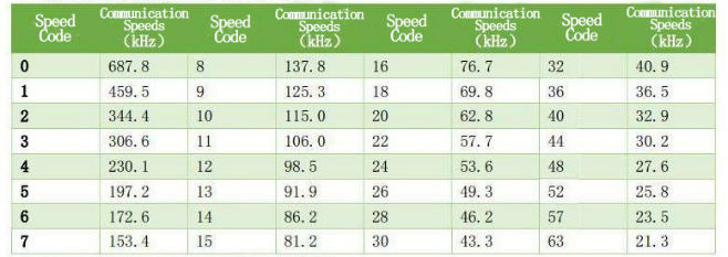
· IIC speed codes and measured speeds at clock divider 8
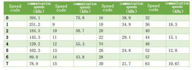
· IIC speed codes and measured speeds at clock divider 1
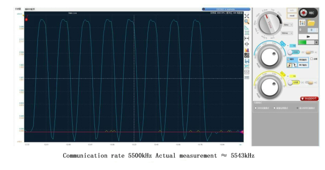
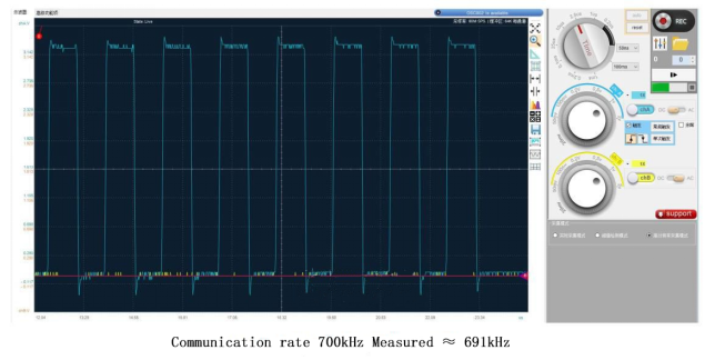
· SPI speed codes and measured speeds at different clock dividers

3. SPI Communication Parameter Settings
Default SPI parameters are 700kHz, MSB, L, B. You can modify them using the command: [STSPI] baud xSB po ph
· baud: Communication speed in kHz; options are 5500, 2700, 1400, 700
· xSB: Data transfer order, MSB or LSB first
· po: Clock polarity, where H = idle SCK high, L = idle SCK low
· ph: Clock phase, where F = data output on the leading clock edge, B = data output on the trailing clock edge
Note: After executing, the registers BAUD_SPI and ISCW_XSB are updated synchronously but not saved.
Note: System clock divider affects I2C and SPI communication speeds.
4. Modify System Parameters
Use the [SYSP] command to change other system parameters. The command format is: [SYSP] Addr ECHO DEBUG_MSG UART12_TT CLKDIV
· Addr: Device address
· ECHO: Whether to echo received data (1 = yes, 0 = no)
· DEBUG_MSG: Whether to output debug messages (1 = yes, 0 = no)
· UART12_TT: Whether UART1 and UART2 operate in transparent transmission mode (1 = yes, 0 = no)
· CLKDIV: System clock divider
Example: [SYSP]12 1 0 1 1
This sets the device address to 12, enables data echo, disables debug messages, enables transparent transmission between UART1 and UART2, and disables clock division.
5. Saving Parameters
All parameter changes take effect immediately but are not saved after power-off. To save the current parameters permanently to EEPROM, use the [SAVE] command.
6. Parameter Reset
There are two ways to reset parameters:
· Send the [STDEF] command via the UART interface to the module
· Before powering on the module, connect the FUN jumper cap to GND as shown in the diagram below. After reset, switch the jumper cap to pins 2 and 3 to prevent repeated resets.
AT24Cxx / GD25Qxx
Note: The third-row pins from left to right are GND, FUN, and empty. Connecting pins 1 and 2 with a jumper forces FUN low. If FUN is detected low during power-on, system parameters are reset. Connecting pins 2 and 3 leaves FUN floating (internally weakly pulled high).


