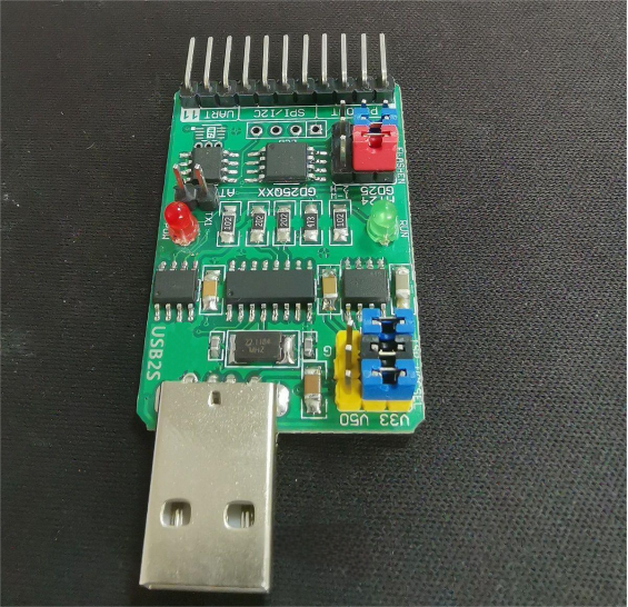
In the previous two DIY articles — DIY: USB2S Adapter Setup Tips & Common Issues and DIY: USB2S Adapter Size & Voltage Setup — we discussed common problems and important considerations for the programmable USB-to-UART/I2C/SMBus/SPI/CAN/1-Wire adapter USB2S, as well as its physical dimensions and voltage settings. In this DIY article, we will detail the interfaces and functions of the programmable USB-to-serial adapter development board.
The programmable USB-to-UART/I2C/SMBus/SPI/CAN/1-Wire adapter USB2S (USB To Serial ports) acts as a multi-protocol physical layer forwarder. It comes with powerful and flexible S2S protocol firmware and supports embedded C language development. It enables bi-directional communication between USB interfaces and serial ports, as well as between different serial ports, across Windows, Android, and WinCE operating systems. Additionally, it can be used for pulse counting, digital oscilloscope functions, and voltage comparison. It is widely applied in electronic device development, chip testing, industrial digital interface conversion, and digital interface learning and verification.

1. UART Interface
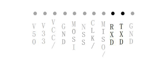
This module features two UART interfaces named UART1 and UART2. UART1 refers to the COMx serial port that appears on the computer after the USB connection; this port enables communication between the computer and the USB2S. UART2 refers to the external UART interface on the USB2S board itself (TXD and RXD pins).

Pins 9 and 10 are the RXD and TXD lines of UART2 asynchronous serial port respectively. RXD is a weak pull-up input, and TXD is a strong push-pull output.
The UART communication speed ranges from 1200bps to 921600bps and supports configurable data parity and stop bits. The default baud rate is 9600bps.
2. LCD Interface
The board provides a reserved LCD screen interface based on the I2C protocol. Compatible screens operating at 3.3V or 5.0V can be optionally connected.
3. MCU
USB2S uses an STC microcontroller as its programmable core, featuring 2kB RAM, 4kB EEPROM, and 16kB FLASH. It is built on an ultra-high-speed 1T (one cycle instruction) 8051 core. The MCU supports sleep mode, pulse signal wake-up, timer wake-up, 5 16-bit timers, 1 voltage comparator, 4 external interrupts, and hardware I2S, SPI, and UART interfaces. It also supports online in-circuit debugging.
4. Firmware
The built-in firmware enables transparent data transmission between different serial interfaces and can parse and forward data according to predefined communication protocols. By modifying internal register parameters and using PC software tools, you can perform nearly all types of serial interface test applications.
MODBUS communication protocol is embedded.
This allows you to develop your own firmware based on the provided sample routines.


