
In the previous DIY article DIY: ZOYI ZT-C1 Teardown & Upgrade Guide, we covered the teardown of the ZT-C1 portable auto-ranging multimeter and how it can be upgraded to the ZT-C2. In this follow-up, we'll continue exploring this auto-ranging meter by comparing the performance of the ZY-C1 against the VC890C+ across various test ranges.
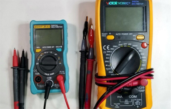
As shown in the image below, the ZT-C1 is noticeably more compact compared to the VC890C+.
When not in contact, the C1's voltage range returns to zero properly.
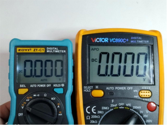
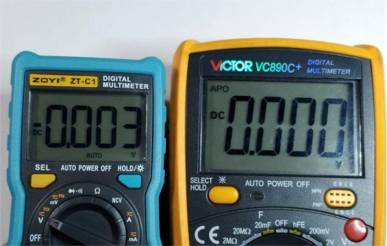
However, if you tap on the casing with your finger, the last digit on the C1 may jump around, while the VC890C+ doesn't have this issue. If this bothers you, you might consider adding shielding to the C1 later on.
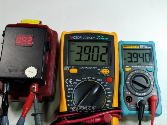
Since there wasn't time to calibrate using a known voltage source, we compared it against the VC890C+ which was modified to display up to 9999.
C1 has a 3999 display, and when measuring a voltage around 3.9V, it reads slightly higher than the VC890C+.
Next up is the measured voltage value during range switching on the C1.
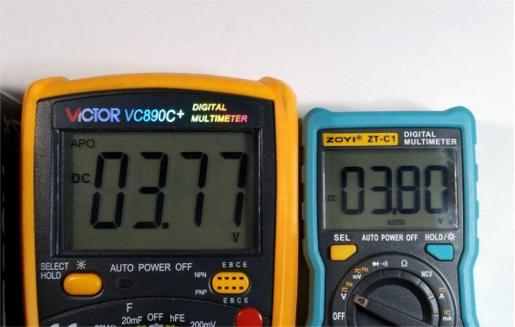
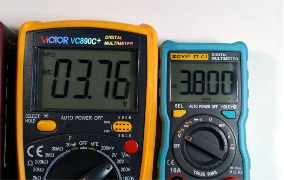
It's clear that the 4V range switches down when the voltage drops below about 3.8V.
Measuring 220V AC also shows a reading that skews high.

Now let's move on to resistance testing.
All resistors tested are 0.01% tolerance and still within spec. Each was measured and then swapped for double-checking.
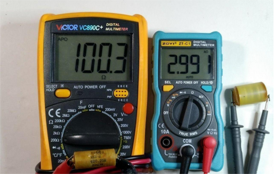
100.25Ω resistor: VC890C+ reads 100.3, C1 reads 100.9
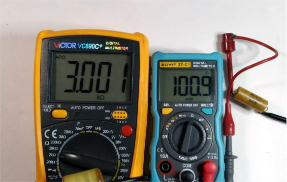
3kΩ resistor: VC890C+ reads 3.001, C1 reads 2.991
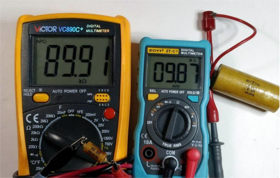
89.8kΩ resistor: VC890C+ reads 89.91, C1 reads 89.4
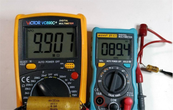
9.9MΩ resistor: VC890C+ reads 9.907, C1 reads 9.87
Now for current testing.
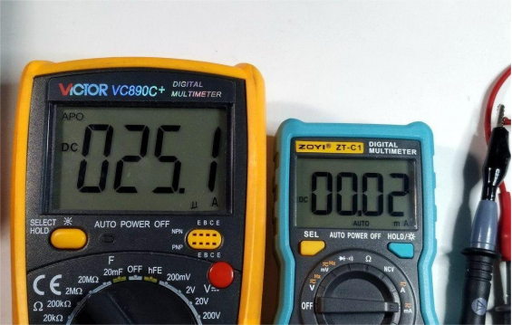
Since the C1 only resolves down to 0.01mA, it can't measure the 25μA current.
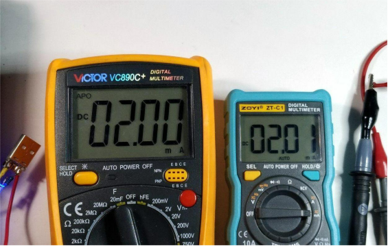
At 2mA, the readings are fairly close.
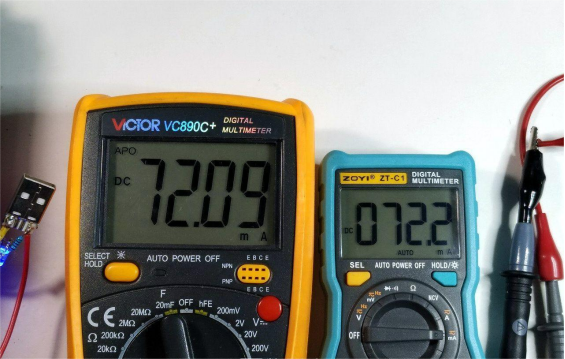
At 72mA, the C1 still shows a slightly higher value.
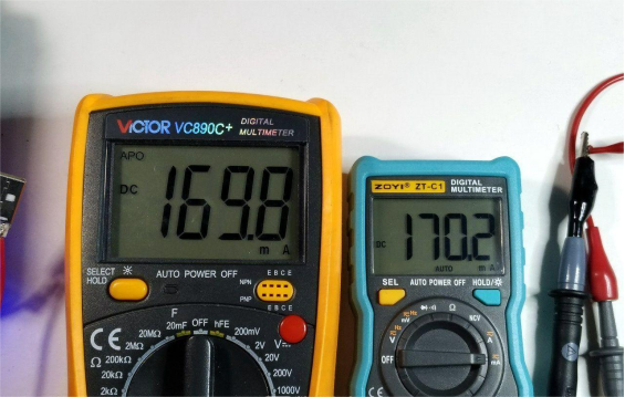
Same goes for 170mA.
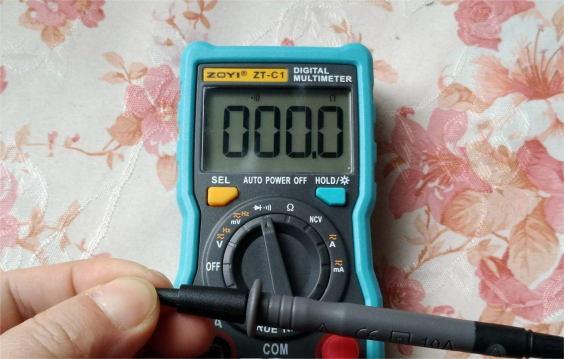
Next, in diode mode, shorting the probes correctly returns to zero.
Since the battery setup is 2xAA, an output of just over 2V is normal. However, this also means it can't drive high-power LED beads.
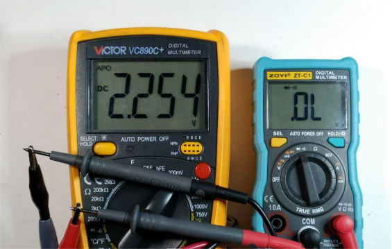
The VC890C+, modified with a lithium battery, outputs close to 3.3V.
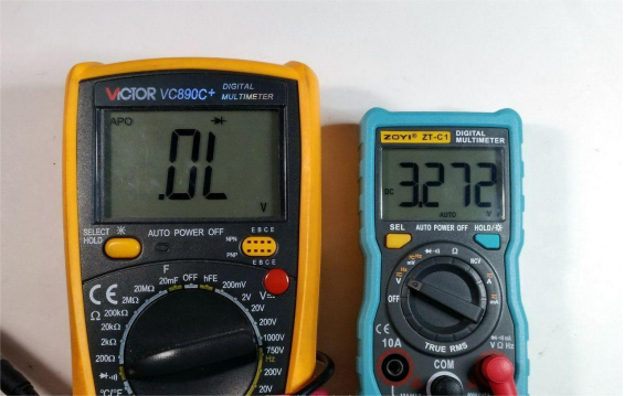
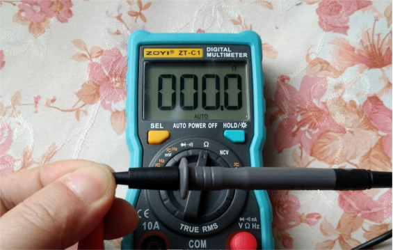
Shorting the leads in resistance mode also returns to zero correctly.
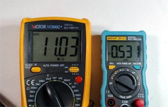
Measuring the output voltage in resistance mode shows it's around 1V as expected.
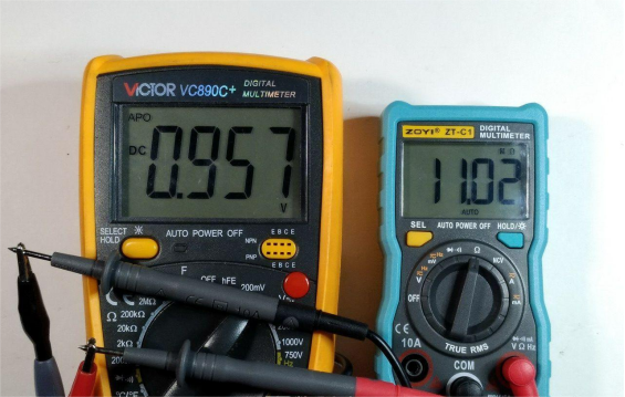
Compared to the C1, the VC890C+ outputs slightly lower voltage in resistance mode.
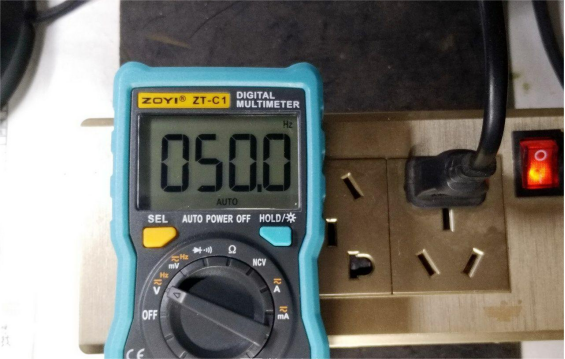
When measuring frequency, the probe easily picks up 220V AC signals just by being near it.
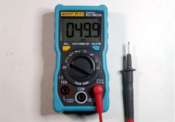
Even without inserting the probe, placing it on a power strip still triggers detection, which indicates poor anti-interference capability.
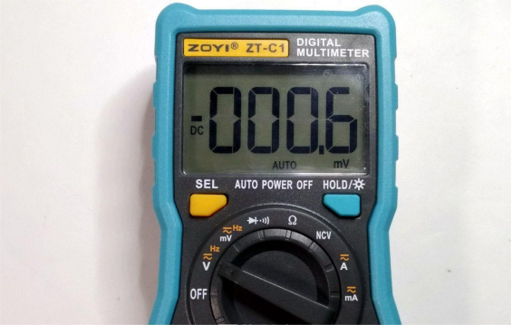
A minor issue: after switching voltage ranges, the lowest available range becomes millivolts.
The main controller is likely the SD7830A by Huajing (Altek Corporation). Information such as pin functions, internal block diagrams, and application circuits can be found online.
From this comparison, the ZY-C1 tends to give slightly higher readings, with the largest deviation being around 1%. That said, a 1% error isn't a significant problem overall.


