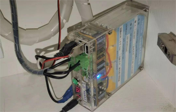
In everyday life, power outages are pretty common. When the power goes out, of course, your network equipment and surveillance devices won't work either. So how can you set up an uninterruptible power supply? If you're curious, take a look at this article.
You might be wondering why not just use a power bank. The reason is that most power banks on the market only output 5V. A few support fast charging with adjustable voltage, but almost none allow simultaneous charging and discharging. They also have low power, usually only 20–30W, which is far from enough to act as an uninterruptible power supply for high-power devices. The few high-power power banks that do exist are expensive, have messy interfaces, are inconvenient to use, and still may not support simultaneous charging and output.
So if you also want an uninterruptible power supply, follow this article to DIY your own.
Here's what the finished product looks like:
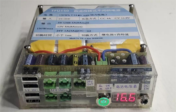
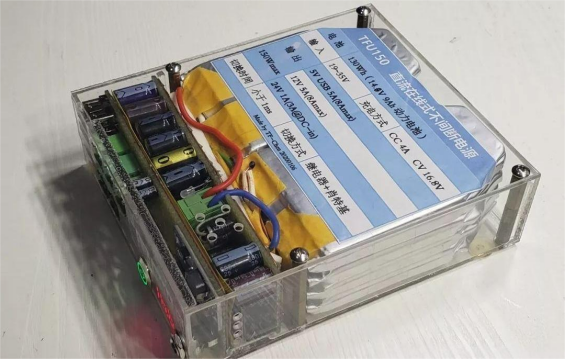
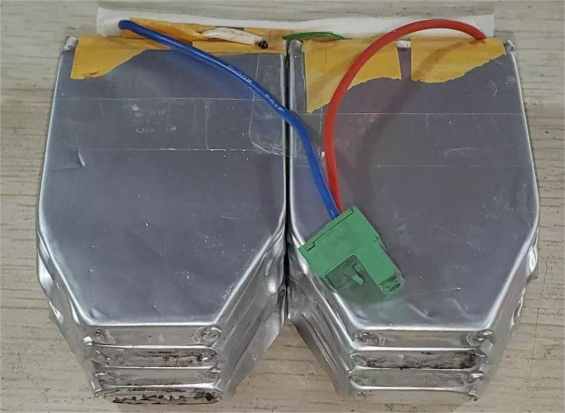
To make an uninterruptible power supply, the first thing you need is a battery. High-capacity, high-power lithium batteries are the best choice. If you happen to have a spare drone battery, you can take out eight 3.7V 4.5Ah cells and connect them in series and parallel to make a 14.8V 9Ah, or 130Wh, battery pack.
Next, you'll need a DC-DC module for charging and discharging. The main outputs should be 5V USB and 12V. You can use the 3R35 module. This module is compact but powerful, can output 5A continuously, and up to 8A for short bursts. It uses synchronous rectification, making it very efficient, and the main chip is the TPS40057.
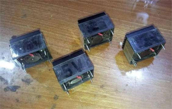
Modifying the module is very simple. You just adjust a few resistors to get the voltage you need.
For an uninterruptible power supply, the key is supporting simultaneous charging and load powering. It also needs to switch immediately to battery power if the input is disconnected. Lithium batteries need constant current followed by constant voltage when charging, so current detection is necessary. Usually, a very low-value shunt resistor is used to convert current to voltage, which the control chip uses to adjust the current.
However, most constant current/constant voltage modules you can buy use negative-side current sensing. This won't work in a UPS system because all the negative terminals in a UPS share the same ground. If you sense current on the battery's negative side, the shunt resistor gets shorted, the battery cannot charge properly, and it could be dangerous. So you need to build a positive-side current sensing circuit yourself. It's very simple—just use an op-amp differential amplifier circuit. As long as the op-amp supply voltage is higher than the sensed voltage, it works. Like this:
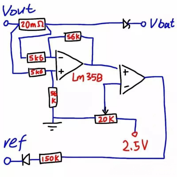
Using this method, you can turn any ordinary DC-DC constant voltage module into a constant voltage/constant current module with positive-side current sensing. The downside is that the current adjustment isn't very linear, but since we're only using it for charging and don't need to adjust current, this circuit is perfect. So in this setup, you'll still use the 3R35 module to charge the battery.
When it comes to switching between input and battery, there are three common methods: relays, diodes, and MOSFETs. Relay switching is cheap but has noticeable delay. Diode switching has no delay, but voltage drop causes power loss and heat. MOSFET switching is the most efficient but requires a specialized control chip and is expensive. You can choose a relay + diode switching method. Use a Schottky diode to provide a current path during the tiny gap (tens to hundreds of milliseconds) when the relay contacts open, ensuring uninterrupted power.
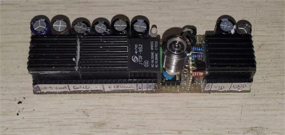
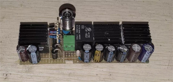
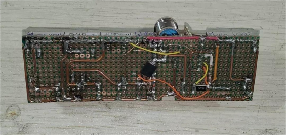
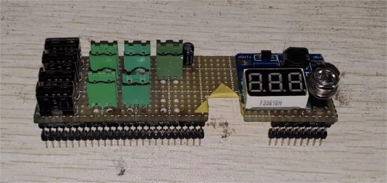
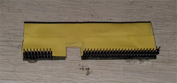
At this point, all the circuit modules are built. The circuit is simple—you can make it on a protoboard. Make a separate small board for the interfaces and stack it with the other modules to maximize space usage. Combined, it looks like the picture above. Since there's extra space on top, you can even add a boost converter to provide a small 24V 1A output.
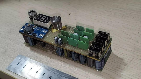
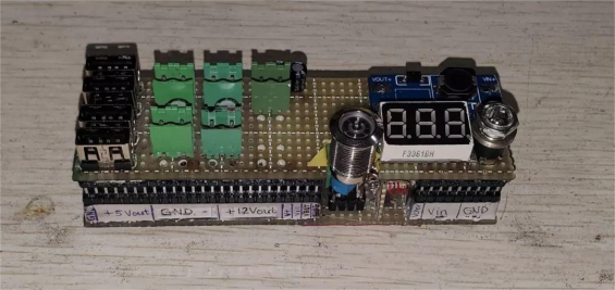
Next, you need to make a case. Acrylic is a good choice because it's easy to work with and fairly sturdy.
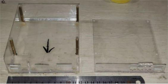
Install the battery and circuit boards into the case, and you're done!
Specs summary:
· Battery: 130Wh (14.8V 9Ah Li-ion)
· Input: 19–35V
· Charging: CC 4A, CV 18.8V
· Output (max 150W): 5V USB 5A (8A max); 12V 5A (8A max); 24V 1A (3A @ DC-in)
· Switching time: <1ms
· Switching method: Relay + Schottky diode
Then plug in your modem, router, switch, cameras, NAS, and all other devices, and you're ready to go.
