
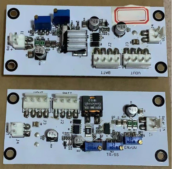
If you're interested in DIYing a CCCV solar charge management system using the LT8613, you might want to check out this article.
If your house is fairly large and you use an optical modem, a router, and home cameras, and you also need lighting in your yard at night, you'll want to set up a low-voltage solar power system.
If this sounds interesting, you can follow along and DIY this low-voltage solar setup with me.
The LT8613 handles CCCV solar charge management and comes with a simple MPPT. You can refer to its datasheet and online LT8611 solar circuit examples.
For this DIY project, you'll need 21 Panasonic 18650 batteries with 3400mAh each (we've tested 3200mAh too, which works), arranged 7 in parallel and 3 in series. That's roughly 23.8Ah. Because long-term high-voltage float charging is bad for batteries, you should set the LT8613 charging voltage to a maximum of 12.45V @ 5A.
For the solar panel, you can use an 18V 120W panel.
Efficiency calculations are as follows:
At a 2A charging current: output = 24.8W / input = 25.848W (18V * 0.718 * 2) = 0.95945, which is about 96%. Super high efficiency.
At a 4.9A charging current: output = 60.5W / input = 64.656W (18V * 1.796 * 2) = 0.9357, about 94%. Efficiency is still very good.
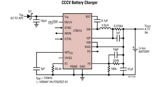
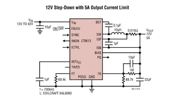
As an example, consider what happens when a well-lit 1W solar panel with a Vmp of 9V is connected to this circuit and a Li-Ion battery sitting at 3.8V. When enabled, the LT8611 will try to raise the output voltage to 4.1V at up to a maximum of 1A. Since the 1W panel can't provide that much power, the panel voltage will drop below its Vmp to just above the battery voltage plus the forward voltage of diode D1.
Input voltage regulation is added to this circuit so the LT8611 can reduce the battery charging current and keep the solar panel operating at its maximum power point. First, let's look at what happens if we add a resistor divider from the input voltage and feed the midpoint to the TR/SS pin of the LT8611, as shown below:
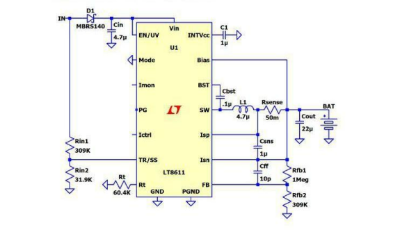
The LT8611's output error amplifier has an internal 970mV reference. The output divider in this circuit is sized so that the FB pin reaches 970mV when the battery hits 4.1V. When the battery is at 3.8V, the FB pin reads 900mV due to the output voltage divider. The LT8611's tracking feature ensures that if the TR/SS pin is below 970mV, the FB pin is regulated to match the TR/SS voltage. If the resistor divider is sized so that TR/SS reads 900mV when the panel voltage is at its 9V maximum power point, the LT8611 tracking will lower the output voltage (and thus the battery charge current) to maintain a 9V input when the battery is at 3.8V. At this point, the circuit has an input regulation or MPPC loop that depends on battery voltage, which isn't very useful. For a microcontroller to run a solar panel MPPT scan, it must control the input regulation voltage.
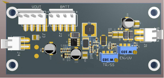
Done.


