
If you're interested in DIY-ing a stacked 4056 charger that can handle 2A charging, you might want to check out this article.
You'll need to prepare all the parts in advance, as shown in the picture below: a battery holder, 4056 charging boards, AD4056ES, and 0603 122 resistors.
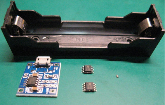
The battery holder is a single-slot 18650 holder with pins. The casing is thick and durable, and the spring is strong enough to ensure good contact with the battery.

The 4056 charging board—you can also use a 4056 board with a better IC.

If you can't find a better IC, you can replace it with the AD4056ES. It has two advantages: precise cutoff with low dispersion and reverse polarity protection so the IC won't burn out.

When replacing the IC, you can do it on a PTC heating station. After replacing the first AD4056ES, the second one needs some pin adjustments: pins 2, 6, and 7 stay as they are; pins 1, 3, 4, 5, and 8 are bent down to prepare for stacking with the first 4056ES.

You can pre-apply a little thermal paste, which helps with heat dissipation after stacking.
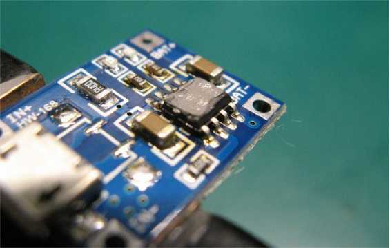
Use 0.3mm solder for better control over the solder on the pins. After stacking and soldering, try to apply a bit more solder to each pin, which helps with current flow, as shown below.
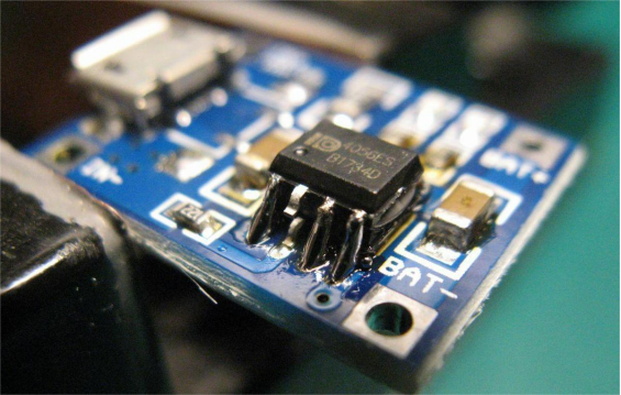

Next, you need to solder the 122 resistor to pins 2 and 3. Soldering this is delicate work—don't rush. The 122 resistor is used by the 4056 to control the output current, giving a 1A output.

Then you need to bend the battery holder pins, tin them, and solder the wires.

Next, solder the wires to the 4056 board.

Then, put a heat shrink tube over the board for insulation and use a heat gun to shrink it, as shown below.

After that, attach the 4056 board to the battery holder. You can use silicone thermal adhesive—it's heat-resistant and flexible. AB glue, hot glue, or structural glue are not heat-resistant and are not suitable here. Pre-apply some on the mating surfaces.
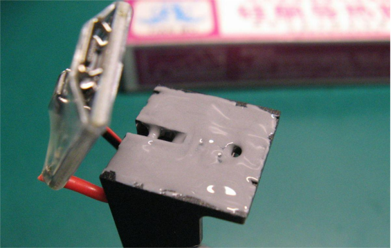
You can use a spring clip to hold it in place and let it set for a day.

Once the adhesive is fully cured, the board and battery holder will bond firmly.

You'll also need some super-sticky double-sided foam tape to fill the bottom of the battery holder, as shown below.

Then, cut a piece of stiff cardboard for the base. Measure carefully before attaching the base, and you can also make a "skirt" using electrical tape.
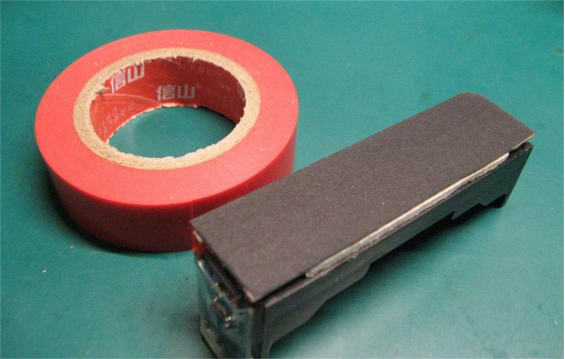
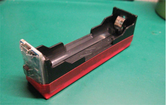
Use a craft knife to slowly cut off the heat shrink on the 4056 board, which will help with heat dissipation.
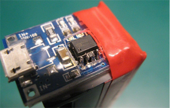
Next, you can get ready to charge. The battery is a 2000mAh 18650.

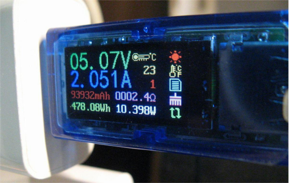
When charging starts, the output current from the charger looks like this:
As shown below, the charging red light turns blue.

You might think it's fully charged, but it actually isn't. Among the two 4056ES chips, one will cut off and trigger the LED when its output current drops to the threshold, while the other will continue charging the battery until it also reaches the threshold.

Only when both 4056ES chips cut off will the charger truly stop.
During charging, the current drops from 2A to 1A in about 45 minutes. Then, it goes from 1A to both channels cut off in roughly 75 minutes. For a 2000mAh battery, the entire charging process takes about 2 hours.

To summarize this stacked 4056 charger:
Pros: Easy to source materials, cheap, simple to make, and works well.
Cons: Stacked chips do get hot. Fortunately, the 4056 has internal temperature control, so in extreme overheating, it will automatically reduce output current to protect the chip.
Done.


