DIY Spectrometer: Build a Simple USB Spectrometer


If you are interested in making a DIY spectrometer, you may want to check out this article.
If you happen to have a DVD disc, a USB camera from an old laptop, and a toy gun scope (to reduce the impact of internal reflections), you can start building your own device.
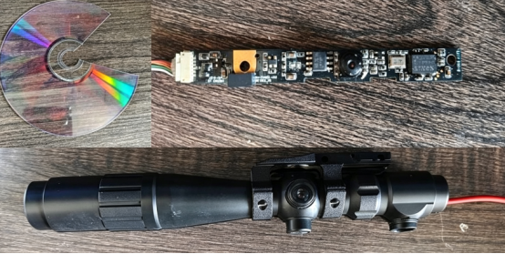
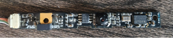
This is a USB module removed from an old laptop. First, remove the LED, find a USB data cable, identify the four wires, and solder them in the correct order (VCC red, GND black, D+ white, D- green/gray). Then plug it into your computer to check whether it works properly. If D+ and D- are soldered in reverse, the device may not be recognized. Simply swap the wire order to fix it.
You can make the diffraction grating from a DVD disc. A DVD usually consists of two layers. Open a small cut from the edge and separate the two layers. You need the transparent upper layer. Cut out a small piece from it, preferably close to the edge of the disc. The curvature of the diffraction grating will be smaller in this area, so the resulting spectral lines should be relatively straight. The general idea is shown in the figure.
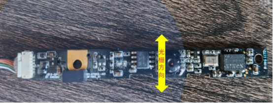
Cut a small piece from a foam board. Mark the size of the camera in the center and cut out a hole. Then attach the diffraction grating cut from the DVD onto the foam board. You can simply fix it with some glue.
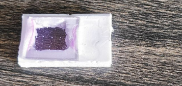
When attaching it, pay attention to the direction. The lines of the diffraction grating should be perpendicular to the long side of the camera.
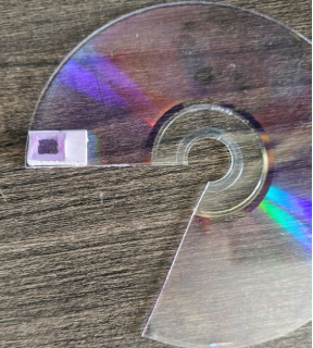
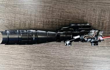
Next, disassemble the toy gun scope and remove all unnecessary parts. After placing the camera module together with the diffraction grating, insert it into the proper position at an angle. Keep the angle between the optical axis and the module at around 30 degrees.
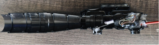
The internal structural relationship is shown below.
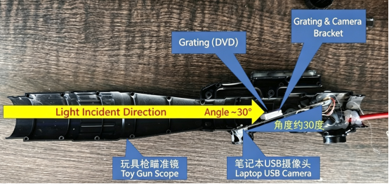
If you are not sure about the position, you can adjust it while shining a flashlight from the scope opening along the optical axis. You can use software on your computer to check whether the image captured by the camera in the upper-right window shows colorful spectral stripes. Try to keep the stripes vertical and as close to the center of the camera image as possible.
You can adjust the direction of the stripes by rotating the diffraction grating. You can adjust the position of the light spot by changing the tilt angle between the camera and the incoming light direction. After confirming the position, fix everything with hot melt glue.
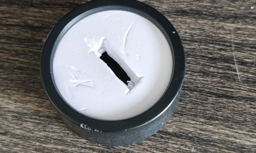
Finally, make a slit at the entrance using a piece of foam board. Try to keep the long edge straight. Generally, the narrower the slit width, the better. However, considering that the camera has relatively low sensitivity and insufficient light intensity may occur, you can make the slit slightly wider. This will reduce the spectral resolution, but it will not significantly affect rough measurements.
When installing it at the front, try to keep the long edge direction parallel to the short edge direction of the camera circuit board, which is also the direction of the diffraction grating lines.
Now you can connect it to your computer and start testing. Before using it, first set the calculation area of the input image based on the position of the spectrum in the camera image. This includes the starting X value (the far left of the box), ending X value (the far right of the box), starting Y value (the bottom of the box), and Y value (the width of the box).
Please note that the Y value here refers to the width, not the coordinate position.
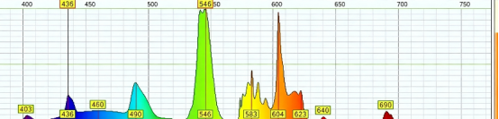
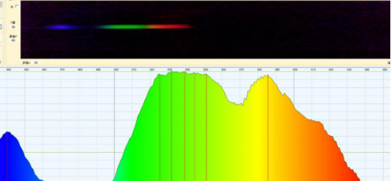
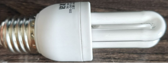
Then perform spectral position calibration. You can use a fluorescent tube for calibration. Use its two sharp peaks at 436 nm and 546 nm as calibration points. If you have another light source with a known spectrum, you can also use it.
This is the spectrum you measured.
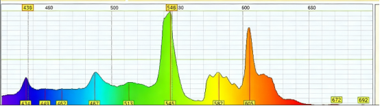
This is the spectrum measured in the instruction manual. Overall, the results are still very consistent.