
DIY Adding a Switch to a Five-Outlet Socket with USB Ports


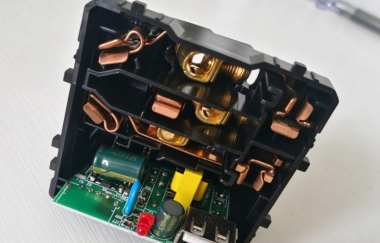
If your bedroom happens to have a five-outlet socket with USB ports, but the USB power supply has no switch, you may notice that the small red indicator light on the socket panel stays on all day and night. If you are worried that something inside might burn out, you might suddenly get the idea of adding a switch to the socket.
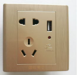
This is the socket in question. The panel appears to have a space where you could install a switch.
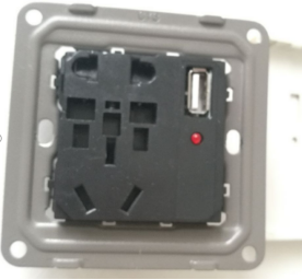
First, remove the outer casing.
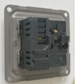
Then, start by releasing the clips on the side.
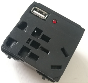
Use a flathead screwdriver to pry open the four clips and remove the power supply module.
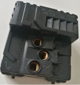
You can see that the USB power supply outputs 5V at 1–2.1A, while the panel is labeled with a current rating of no more than 1000mA.

There are also clips here.
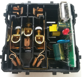
Finally, the casing is open. The internal build quality looks reasonably good.
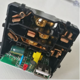
The USB module is clipped onto the copper contacts at the bottom. You can pull it out with a firm tug.
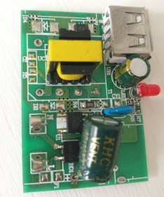
The switching transformer has two mounting positions, and this unit uses the smaller one. Looking at the PCB, you can see that there was originally a USB port in the lower section, but that component was omitted to cut costs. Fortunately, this space is just large enough to accommodate a switch.
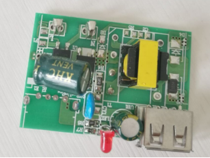
After examining the circuit carefully, you can cut the thin copper trace that replaces the fuse at the input and connect a switch in series. Choose the smallest rocker switch available.
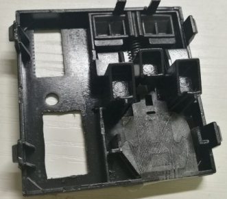
Next, cut an opening in the inner casing. First, use a small electric drill to make a series of holes around the outline. Then, slowly refine the opening with a utility knife and a file.
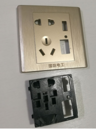
Once you have finished cutting the opening in the inner casing, fit it over the panel and mark the corresponding position. Then, continue cutting the opening in the panel.
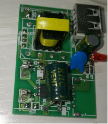
After cutting the copper trace, you can use the solder pads originally intended for a surface-mount fuse on the PCB to connect the switch.
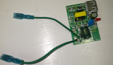
Solder two thin wires to the pads.
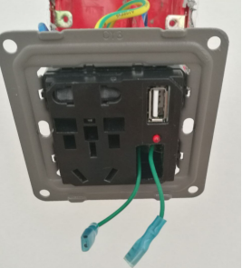
Insert the assembly into the inner casing, reinstall the metal plate, and begin mounting the socket on the wall.
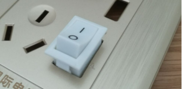
Since the switch terminals protrude quite far from the back, you can press the switch only halfway into place before mounting the socket on the wall.
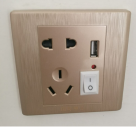
Finally, the switch is installed, and the modification is complete.


