DIY WY815P High-Frequency Soldering Station


After three generations of updates, WY815P high-frequency dual-purpose soldering station was released by Wenyu after the epidemic, which is practical and compact. How to make it a cost-effective high-frequency tool? You can try the following steps.
First, let's take a look at the circuit implementation of the traditional Quick 203:
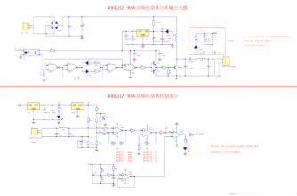
In the circuit, L1 serves as the current source for Q3 while also providing power to the main driving circuit through L2 wound on the same magnetic core, rectified by D1, and stabilized by U1. Initially, the main power is started by energy storage through R1 and C4.
Next, let's examine the driving section. Part C of CD4011, together with the optocoupler, forms the switch control part, which controls the operation of the oscillator formed by part B, drives the totem pole consisting of Q1 and Q2 through parts A and D, and then drives Q3. The output capacitor of Q3, C10, C7, L3, C9, and the coil in the handle together form the output resonant circuit.
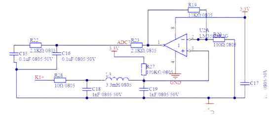
The temperature measurement part consists of R7 and R5, which form a voltage divider circuit to elevate the output potential of the thermocouple. Since the ideal value of the input offset voltage of LM324 is 2mV (maximum 7mV), it means that without elevating the thermocouple, the operational amplifier's response to the K-type thermocouple temperature would require a temperature of around 170 degrees Celsius. Therefore, in this circuit, R7 and R5 are used for voltage division, and a 1K adjustable resistor is parallel connected to R5 to adjust the zero point of the thermocouple.
The voltage after being elevated is amplified in phase by one unit of the 324, then further amplified by the second unit through adjustable gain. Unit D is configured as a follower, with W1 used to adjust the follower voltage, which serves as the reference value for temperature. This voltage is compared with C, and the output drives the optocoupler to control the power section.
It's worth noting that the input section of the thermocouple consists of a filtering circuit composed of L1, C1, and C2, which is also crucial. Without this part, the thermocouple would sense significant high-frequency signals, resulting in improper temperature control.
The reason for coupling L1 with L2 to power the circuit is that when L1 is working, it stores energy. So, when the oscillation part stops and the drive is turned off precisely during the energy storage state of L1's current, a high-voltage pulse will be generated on Q3 through L1. This pulse can even exceed 400V, which may cause Q3 to breakdown. However, by coupling L1 with L2, this portion of energy can be transferred to the capacitor after the power supply D1, effectively avoiding this issue.
Of course, this circuit has several problems: no low-voltage or over-voltage protection, no short-circuit protection, changes in handle sensitivity cause corresponding changes in power, and no follow-up capability. Temperature adjustment using a potentiometer requires considerable experience.
Next, let's try to create an improved version with a similar lower cost:
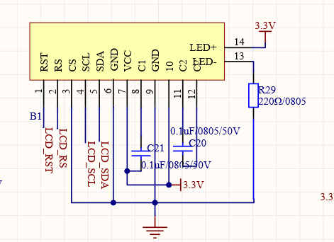
Considering cost and practicality, here we use a 1602 screen with an SPI interface.
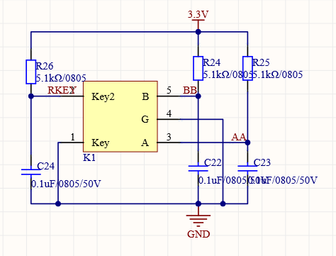
For adjustment, a rotary encoder is used, making it convenient and efficient to adjust.
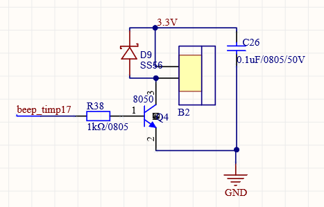
Status indication is essential and including a buzzer is necessary.
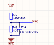
For temperature sampling, cold junction compensation, and amplification, the same method of elevating the thermocouple voltage is used, with slight differences in the grounding method.
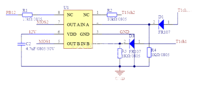
Based on the powerful features of the current microcontroller, there is no longer a need for separate oscillators and phase-locked loops to drive the power section. The microcontroller directly generates complementary PWM signals, and the phase of this PWM is adjusted through current sampling feedback, allowing the power transistors to operate in zero-voltage mode. U1 serves as the MOSFET driver, while D1 and D2 provide safe isolation between the microcontroller's I/O port and the driver.

In the power output section, parallel resonance is used, which requires a constant current source. To simplify the circuit and avoid the complexity of winding the inductor as shown in the previous example, a simple and reliable DRC circuit is employed for energy dissipation. Two MOSFETs in a push-pull configuration are used to drive the resonant circuit, distributing the heat generated by the MOSFETs. T1 facilitates resonance, impedance matching, and isolation, ensuring complete isolation between the soldering iron and the power supply, whether it is a switched-mode power supply or an autotransformer. Of course, when a grounding condition is present, it is advisable to properly connect the outer steel pipe of the soldering iron tip to the ground.
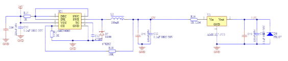
For power supply, the inexpensive and sufficient MC34063 chip is selected.
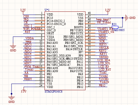
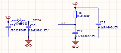
The microcontroller section consists of a typical minimal system circuit.
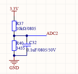
Protection and compensation circuits are implemented for the temperature, current, and parameters of the soldering iron handle. An NTC thermocouple is installed next to the MOSFET to measure its temperature. Although the overall design aims for cost-effectiveness, necessary protection measures are still necessary.
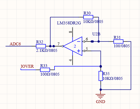
The current sampling section, in conjunction with voltage sampling, enables control of maximum current, power, and phase through programming.
The finished product:
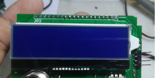
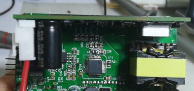
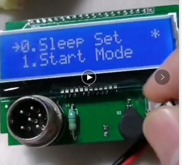
The overall dimensions are small, measuring only 7.9 * 5.2 cm. For fixation, the rotary encoder screw and aviation plug screw are used together to secure the circuit board to the housing. It is suitable for a wide range of enclosures. The power supply voltage can range from 22-36V, and it can be powered by a switched-mode power supply or an autotransformer (requires an external rectifier bridge). Alternatively, it can be powered by batteries, with battery voltage protection settings included in the program. The peak output power is 120W, and it comes with overheat protection and a self-starting cooling fan. It is compatible with standard 203 high-frequency soldering iron handles.
In terms of programming, it allows for setting the sleep time, sleep temperature, shutdown time, activation mode, battery voltage range, and also features PID control, enhancing the circuit's versatility.
The choice of high frequency is due to its excellent performance and affordability:
1. The soldering iron tip directly heats up under the action of eddy currents, eliminating the additional thermal resistance introduced by conventional insulation materials.
2. The thermocouple is placed directly on the inner side of the soldering iron tip, accelerating temperature sensing.
3. Most importantly, the soldering iron tip is inexpensive and durable.


