
If there In the previous two DIY articles — DIY: ZOYI ZT-C1 Teardown & Upgrade Guide and DIY: ZT-C1 vs VC890C+ Multimeter Test — we explored the internal structure of the ZOYI ZT-C1 portable auto-ranging multimeter and compared its performance across different measurement modes. In this article, we'll walk through how to fix the ZT-C1's erratic readings in the low-voltage range, and as a bonus, add a temperature measurement feature. If you're interested, read on!
The issue with unstable readings in the ZOYI ZT-C1's low-voltage range could be due to interference. If, upon opening the unit, you find that the back cover lacks a common shielding layer, you can try adding one yourself.
Additionally, the V range on this meter can switch to mV mode — not sure if that's a bug or an undocumented feature. If you figure out a fix, feel free to implement it on your own.
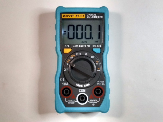
Back to the main topic — you'll want to start by removing the LED used for the flashlight feature to prevent unnecessary power consumption when the backlight is on.
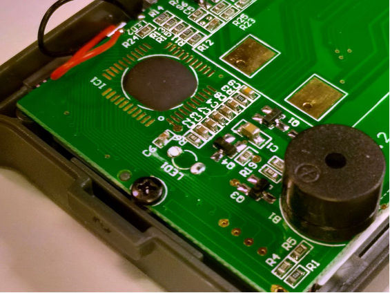
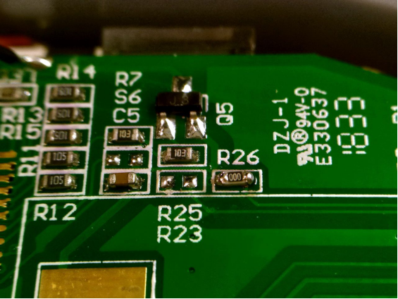
To add a temperature measurement function, you'll need to modify resistors R23 and R26.
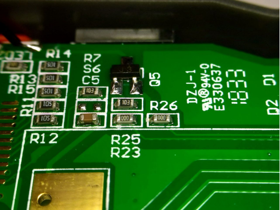
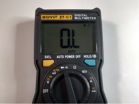
You can start by removing R26 and observe any changes.
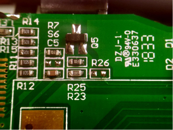
You'll notice that the diode mode now includes resistance measurement, while the original resistance mode remains unchanged.
Next, solder R26 back in and remove R23.
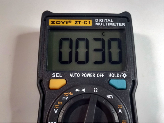
After this modification, the resistance mode becomes the temperature mode (the display reads around 30°C at room temperature without a thermocouple connected), while the diode mode remains unaffected.
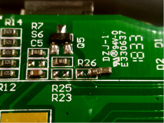
If R23 and R25 control separate functions independently, you can simply remove both R23 and R26.
Now for the main part — if you're planning to use aluminum foil tape as shielding, be aware that its adhesive may not be conductive, meaning it won't form a proper electrical path when pieces overlap. Instead, use copper foil tape.
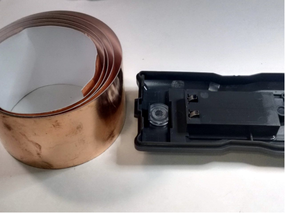
Cut two large pieces and several smaller ones, then stick them to the inside of the back cover.
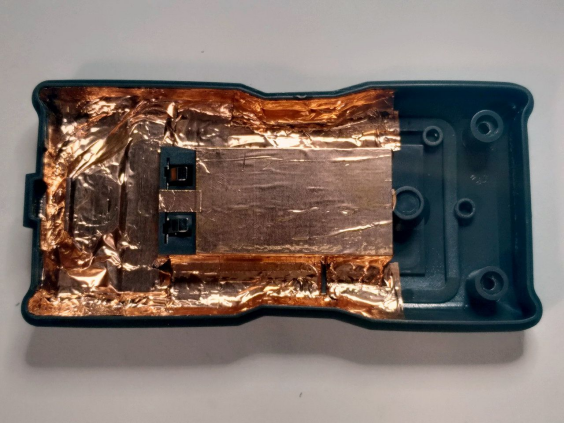
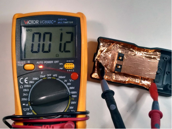
Once applied, you'll need to test and confirm that the shielding is electrically continuous.
You'll also need to solder a spring onto the PCB's large ground plane (this copper area connects to the COM terminal but not to the battery's negative terminal). This spring will act as the contact point.
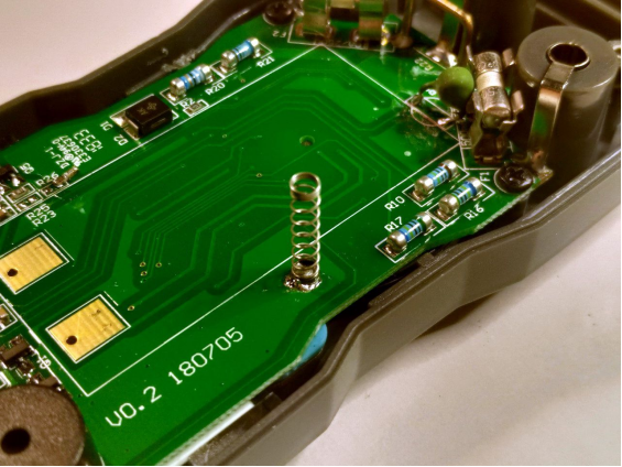
To be extra cautious, cover the PCB with transparent tape to prevent short circuits.
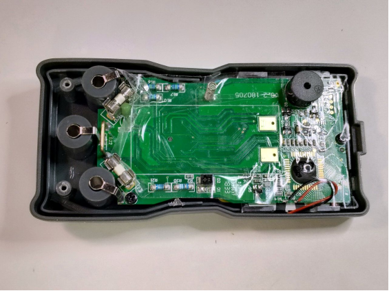
Once that's done, you can close the case back up.
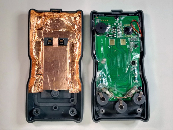
After testing, you should notice that the mV range is now much more stable — fluctuations are reduced to just around 1mV, a significant improvement.
However, keep an eye on the NCV (Non-Contact Voltage) mode. If it stops responding entirely, it might be because the shielding is too effective and blocks detection of ambient electric fields.
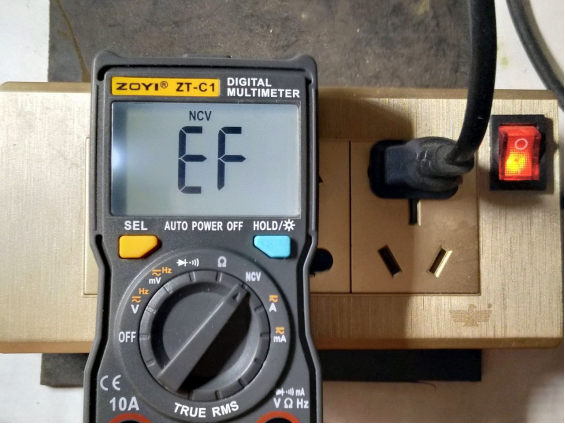
If that happens, open the unit again and cut away the copper tape covering the NCV sensor wire area.
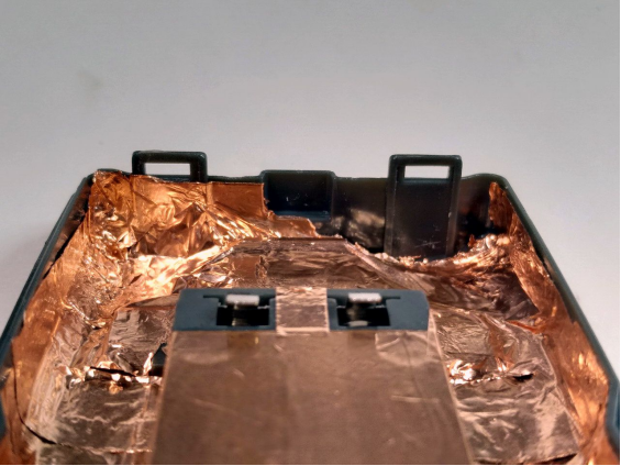
Once done, the NCV function should be restored.
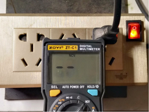
Finally, reassemble everything — and you're done.
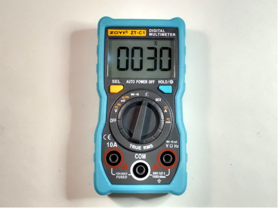
This method, while time-consuming and labor-intensive, does yield results. Of course, there's a shortcut: insulate the PCB with transparent tape first, then stick on either aluminum or copper foil tape, solder a wire, and you're good to go. The outcome should be more or less the same.
All done.


