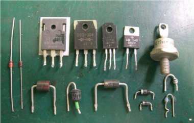
In industrial control, household appliances, and automation systems, using a transistor to drive a relay switch is a cost-effective and widely applied circuit method. The key principle is to operate the transistor in either the saturation region or cutoff region, allowing it to function as a switch that controls the relay's engagement and release. Control signals, such as those from a microcontroller (MCU), typically have limited current and cannot drive the relay coil directly. Therefore, a transistor is inserted between the control signal and the relay coil to act as a switch. At the same time, a base current-limiting resistor, a pull-down resistor to prevent floating, and a diode across the relay coil are needed. This article will explain in detail how to select and calculate the resistors, transistor, and diode in this typical drive circuit.
Catalog
2. Base-Emitter Resistor R Selection
I. Definition
Before discussing selection and calculation, it is necessary to understand the role of the key components. The transistor is a semiconductor device commonly used in amplification or switching circuits. In this application, it acts as a switch to control the relay. The relay is an electromagnetic switch that generates a magnetic field through coil current to drive the contacts. Resistors limit current to protect the transistor from overcurrent damage. Diodes are usually connected across the relay coil as flyback diodes to absorb reverse voltage and prevent voltage spikes from damaging the transistor. The coordinated operation of these components ensures the efficiency and safety of the driver circuit.
II. Selection and Calculation
Correctly selecting resistors, diodes, and transistors is the core of circuit design. The following steps explain how to calculate and choose these components, focusing on the base resistor, base-emitter resistor, transistor, and diode. The calculations are based on typical parameters such as supply voltage, relay coil current, and transistor current gain.
1. Base Resistor RB Selection
The main function of the base resistor RB is to limit current. On one hand, it protects the MCU IO pin from exceeding its maximum output current. On the other hand, it ensures that the transistor operates in saturation mode. The saturation condition is β * IB > IC, where β is the transistor current gain, IB is the base current, and IC is the collector current. The steps to calculate RB are as follows:
First, determine the maximum collector current IC_max: IC_max = (Vcc - Vces) / R_relay
Vcc is the supply voltage, Vces is the collector-emitter voltage drop when the transistor is saturated (found in the transistor datasheet), and R_relay is the equivalent resistance of the relay coil (found in the relay datasheet).
Next, calculate the minimum base current IB_min: IB_min = IC_max / β_min
β_min is the minimum current gain of the transistor (from the datasheet).
Finally, considering the maximum output current of the MCU IO pin I_IO_MAX (from the MCU datasheet), the RB resistor should satisfy: RB = (Vin - Vbe) / IB_min
Vin is the MCU output voltage, such as 5V, and Vbe is the base-emitter voltage of the transistor (typically 0.7V for silicon). Also, ensure that IB_min does not exceed I_IO_MAX to avoid overloading the MCU.
2. Base-Emitter Resistor R Selection
The resistor R connects between the base and emitter and is mainly used to prevent false triggering, ensuring the transistor reliably turns off when the input signal is low. Its value should not be too small, otherwise the transistor may partially conduct while it should be off. The calculation is based on the transistor's turn-on voltage Vbe_on (typical 0.7V for silicon):
Condition: When the input voltage is low, the base voltage must be below Vbe_on. Assuming the input low level is 0V, noise in the actual circuit may exist, so the voltage division condition should be: 5V * R / (R + RB) > Vbe_on
Typically, R is selected between 10kΩ and 100kΩ, depending on actual circuit tuning, but it should not be too small to avoid unnecessary current consumption.
3. Transistor Selection
When selecting a transistor, the current and voltage parameters must be considered to ensure reliable operation in switch mode:
Current capability: The maximum collector current IC_max of the transistor should be greater than the actual collector current in the circuit (calculated IC_max). This parameter can be found in the datasheet.
Voltage rating: The maximum collector-emitter voltage Vceo of the transistor should be greater than the supply voltage Vcc to prevent breakdown. For example, if Vcc is 12V, choose a transistor with Vceo above 15V.
Other parameters: Include the saturation voltage Vces (should be low to reduce power loss) and current gain β (to ensure consistency). Common models include 2N2222 or BC547, which can be selected according to actual requirements.
4. Diode Selection
The diode protects the circuit and prevents high voltage generated by the relay coil when switched off from damaging the transistor or MCU. When the coil current suddenly stops, it induces reverse EMF, and the diode absorbs this energy by clamping it. The key parameters for selecting the diode are:
Reverse voltage: The diode's reverse breakdown voltage should be higher than the supply voltage Vcc to ensure it is not damaged by induced voltage.
Forward current: The maximum forward current of the diode should exceed the maximum collector current IC_max to handle transient current.
Type: Fast recovery diodes or Schottky diodes are often used to improve response speed. Common choices include the 1N4148 or 1N4007 series.
III. Conclusion
Correctly calculating and selecting the components in a transistor-driven relay circuit is the foundation for long-term reliable operation. Designers need to carefully consult the official datasheets of the MCU, transistor, and relay to obtain accurate parameters and perform calculations accordingly. Following these steps can effectively avoid common issues such as insufficient driving capability, transistor overheating, and component damage, resulting in an efficient and reliable electronic switch control circuit.


