
What Causes Relay Oscillation and Capacitor Failure?


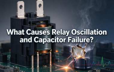
In power control, motor drives, and industrial automation circuits, voltage spikes, transient overvoltage, or sustained oscillations during relay switching may cause capacitors to overheat, leak, or even rupture. The relay itself is not necessarily the source of the fault. Inductive load back EMF, contact bounce, improper capacitor selection, and inadequate power supply design can all contribute to capacitor failure. Accurately identifying the cause and implementing targeted protective measures are essential for improving circuit stability and extending the service life of electronic components.
Catalog
I. What Is Relay Oscillation and Overvoltage-Induced Capacitor Failure?
II. Main Causes of Relay Oscillation and Overvoltage-Induced Capacitor Failure
III. How to Prevent Relay Oscillation and Overvoltage-Induced Capacitor Failure
I. What Is Relay Oscillation and Overvoltage-Induced Capacitor Failure?
Relay oscillation and overvoltage-induced capacitor failure generally refer to a fault condition in which transient voltage changes or abnormal oscillations occur when a relay energizes, releases, or switches repeatedly. These conditions may expose capacitors to excessive voltage, excessive ripple current, or elevated temperatures, eventually causing bulging, leakage, short circuits, or even rupture.
It is important to note that relay switching does not necessarily cause a voltage increase. Only when factors such as inductance, parasitic parameters, power supply characteristics, or control abnormalities interact may the resulting electrical stress become severe enough to damage a capacitor.
II. Main Causes of Relay Oscillation and Overvoltage-Induced Capacitor Failure
1. Transient overvoltage caused by inductive loads. When a relay disconnects an inductive load, such as a motor, solenoid valve, coil, or transformer, the inductor generates back EMF as it attempts to maintain the existing current. If the circuit lacks appropriate snubber or clamping protection, the transient voltage may exceed the capacitor's rated voltage, damaging the dielectric or causing insulation failure.
2. Relay contact bounce or repeated switching. Relay contacts may briefly bounce during energization and release. If the control signal is unstable, the coil supply voltage is insufficient, or the control circuit is subject to interference, the relay may also repeatedly energize and release. These conditions cause transient voltage and current variations, increasing the electrical stress associated with capacitor charging and discharging and potentially resulting in overheating or damage.
3. Improper capacitor selection or excessive current. If a capacitor has an insufficient voltage rating, inadequate ripple current capability, or operates beyond its permitted temperature range, it may experience internal heating, capacitance degradation, and reduced service life. The risk of damage increases when a capacitor is connected directly to a power source and subjected to high inrush current.
4. Power supply abnormalities and improper circuit parameters. An unstable power supply output, insufficient filtering, excessive parasitic inductance in circuit traces, or an underdamped resonance between a capacitor and an inductor may cause voltage oscillations. In addition, reverse polarity in electrolytic capacitors, the use of unsuitable capacitors in AC circuits, and capacitor aging or manufacturing defects may also lead to bulging or rupture.
III. How to Prevent Relay Oscillation and Overvoltage-Induced Capacitor Failure
1. Select capacitors correctly. Choose capacitors according to the actual operating voltage, transient overvoltage, ripple current, and ambient temperature, while maintaining an appropriate voltage margin. For high-frequency or high-ripple-current applications, carefully check the capacitor's rated ripple current, equivalent series resistance (ESR), and temperature characteristics.
2. Add transient voltage suppression measures. For DC inductive loads controlled by relays, a flyback diode, TVS diode, or other clamping circuit can be installed across the coil, depending on the circuit requirements. For AC loads or transient interference caused by contact switching, an RC snubber or metal oxide varistor (MOV) may be considered. The appropriate solution depends on the load type, switching speed, and acceptable turn-off time.
3. Optimize the relay control circuit. Check whether the relay coil supply is stable and whether the control signal contains noise. Also inspect for poor contact, excessive load current, and relay selection mismatches. Where necessary, introduce suitable filtering, hysteresis, or time-delay control to reduce unnecessary repeated switching.
4. Improve power supply and PCB design. Position capacitors and protective components appropriately, and shorten high-current paths and transient-current loops to reduce parasitic inductance and voltage spikes. If LC resonance occurs, adjust the capacitance, inductance, or damping parameters based on actual measurements rather than simply increasing the capacitor's capacitance.
5. Inspect failed capacitors and surrounding components. If a capacitor bulges, leaks, or ruptures, disconnect the power supply first and ensure that stored energy in the capacitors has been safely discharged. Then inspect the actual operating voltage, ripple current, relay contact condition, and protective circuit performance. Before replacing a capacitor, identify and eliminate the underlying causes of overvoltage or overcurrent to prevent the replacement component from failing again.
IV. Conclusion
Relay oscillation and overvoltage-induced capacitor failure are commonly associated with transient overvoltage from inductive loads, contact bounce, power supply abnormalities, improper capacitor selection, or circuit resonance. Resolving these issues requires more than simply choosing a capacitor with a higher voltage rating or increasing its capacitance. Instead, engineers should analyze the circuit structure and actual waveforms to identify the root cause and reduce electrical stress through proper component selection, transient suppression, control circuit optimization, and sound PCB design. Only by identifying the underlying fault and implementing targeted corrective measures can capacitor failures be effectively reduced and the stability and reliability of electronic equipment improved.


