
How to Test a Photo Triac Coupler?


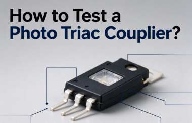
In the electronic components industry, a photo triac coupler is a semiconductor device that combines optical isolation with thyristor switching functions. It is widely used in AC motor control, household appliances, power control, and industrial automation equipment. When a device fails to start, a motor does not run, a load cannot switch on or off properly, or the control system malfunctions, the photo triac coupler may need to be inspected. So, how can you determine whether a photo triac coupler is damaged? What tests can you perform with a multimeter? This article introduces its basic structure, common testing methods, and essential precautions to help you evaluate its operating condition.
Catalog
I. What Is a Photo Triac Coupler?
II. How to Test a Photo Triac Coupler
III. Precautions When Testing a Photo Triac Coupler
I. What Is a Photo Triac Coupler?
A photo triac coupler, also known as a phototriac coupler or optically isolated triac driver, is a semiconductor device that uses light signals to provide electrical isolation between its input and output circuits. Its internal structure typically consists of an input-side light-emitting diode (LED) and an output-side photosensitive triac.
When the input LED receives current and emits light, the photosensitive device on the output side responds to the light signal and triggers conduction in the output circuit. This allows the device to control an external triac or AC load circuit. Because the input and output circuits are optically isolated, the device helps reduce interference from the high-voltage side to the low-voltage control circuit, improving electrical safety and operational reliability.
It is important to understand that a photo triac coupler differs from a conventional optocoupler. Its output is generally designed for AC switching applications, while its specific triggering characteristics, on-state current, and voltage ratings depend on the device model.
II. How to Test a Photo Triac Coupler
A digital multimeter can be used to perform preliminary checks to determine whether a photo triac coupler is functioning properly. Common testing methods include resistance measurement, voltage measurement, and input-to-output triggering tests.
1. Resistance Test
First, completely disconnect the power supply and make sure that all capacitors in the circuit have been fully discharged. Set the multimeter to resistance mode or diode-test mode, and identify the input and output pins according to the device datasheet.
For the input-side LED, use the diode-test mode to check its forward and reverse characteristics. Under normal conditions, the forward test should display a forward voltage drop, while the reverse test will generally show an open circuit (OL). If both directions show an open circuit, the internal LED may be damaged or open. If both directions show a voltage close to zero, the LED may be short-circuited.
For the output-side triac, the main output terminals should generally exhibit high impedance when the device is not triggered. However, internal structures and testing conditions vary between models, so a single resistance reading is not sufficient to determine whether the device is defective.
2. Voltage Test
Voltage measurement is mainly used to check whether the photo triac coupler receives the correct operating conditions in an actual circuit.
First, check whether the input control voltage meets the requirements specified in the datasheet. For example, some control circuits use a 5V DC supply. However, not all photo triac couplers operate with a 5V drive voltage. The LED forward voltage and current-limiting resistor must also be taken into account.
Next, under appropriate electrical safety conditions, measure the AC voltage on the output side and observe how it changes when the control signal is applied or removed. This helps determine whether the load circuit can switch on and off properly.
It is important to note that the output AC voltage depends on the load type, circuit configuration, triggering method, and power supply conditions. Therefore, AC80–170V or AC220V should not be treated as universal reference values for all photo triac couplers.
3. Input-to-Output Triggering Test
To further evaluate the operating condition of a photo triac coupler, you can perform an input-to-output triggering test.
Using a test circuit that meets the device datasheet specifications, apply an appropriate forward current to the input LED through a current-limiting resistor. Then, observe whether the output side can be triggered into conduction. After removing the input drive signal, check the output condition according to the device type and AC circuit characteristics.
If the input LED operates normally but the output side fails to trigger, the internal photosensitive triac may be damaged. However, insufficient triggering current or unsuitable external circuit conditions may also cause this problem.
For models with zero-crossing detection, you should also consider their zero-crossing triggering characteristics to avoid mistaking normal operating behavior for a fault.
III. Precautions When Testing a Photo Triac Coupler
1. Confirm the Pin Configuration. Different brands and models of photo triac couplers may have different pin arrangements and internal structures. Before testing, consult the corresponding datasheet to identify the input pins, output terminals, and polarity correctly.
2. Pay Attention to Electrical Safety. The output side of a photo triac coupler may be connected to AC mains or other high-voltage circuits. Always disconnect the power supply and discharge capacitors before performing resistance measurements. Live measurements should only be performed by qualified personnel using appropriately rated test instruments and protective equipment.
3. Do Not Rely Solely on Resistance Readings. A multimeter has limited test voltage and current, so its measurements are generally suitable only for preliminary inspection. They cannot fully verify the triggering sensitivity, load-handling capability, or voltage withstand performance of a photo triac coupler.
4. Refer to the Datasheet. Different devices have different LED forward voltages, trigger currents, output voltage ratings, and holding currents. Always compare your measurements with the specifications in the datasheet for the exact model rather than applying reference values from other devices.
5. Consider the Effects of External Components. When testing a photo triac coupler while it is still installed on a circuit board, parallel components, resistors, and other circuit paths may affect the measurement results. If necessary, remove the device from the circuit board and test it separately.
IV. Conclusion
You can use a multimeter's resistance, diode-test, and voltage modes to perform preliminary checks on a photo triac coupler. Input-to-output triggering tests can provide additional information about its operating condition. The forward and reverse characteristics of the input LED, the switching behavior of the output side, and the triggering response are important indicators when evaluating whether the device is functioning properly.
However, multimeter testing cannot completely replace professional performance testing. If the device's condition remains uncertain, refer to its specific datasheet and evaluate its trigger current, output conduction capability, and voltage withstand performance. These steps will help you determine more accurately whether a photo triac coupler is damaged.


