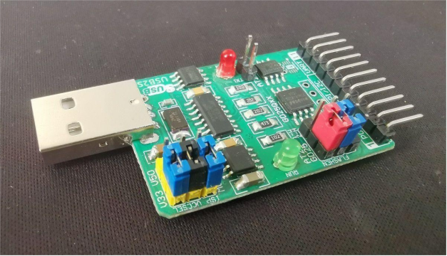
In the previous few DIY articles, we covered the detailed interfaces and functions of the programmable USB-to-serial adapter development board, parameter settings and modifications, as well as USB to UART IIC applications. This DIY article will cover the final related topic for the programmable USB-to-serial adapter development board: the SHT3x-DIS temperature and humidity sensor chip. If you're interested, feel free to keep reading.
Temperature and Humidity Sensor of the Programmable USB to UART/I2C/SMBus/S/SPI/CAN/1-Wire Adapter USB2S: SHT3x-DIS Temperature and Humidity Sensor Chip
1. Chip Introduction

The SHT3x-DIS is a temperature and humidity sensor chip with an IIC interface, capable of operating in either single measurement mode or continuous automatic measurement mode. The USB2S board already includes one SHT31-DIS chip with an address of 0x88.
The SHT3X-DIS outputs temperature and humidity data in 3 bytes: the first two bytes represent the temperature or humidity value, and the third byte is a checksum. The conversion formula is as follows: (Value = Byte 1 * 256 + Byte 2).

Write Command Timing Sequence:
· Send a START signal on the IIC bus
· Send the chip write address (0x88) on the IIC bus
· Send a 2-byte command word on the IIC bus
· Send a STOP signal to end communication
Read Temperature and Humidity Timing Sequence:
· Send a START signal on the IIC bus
· Send the chip write address (0x88) on the IIC bus
· Send a 2-byte command word on the IIC bus, then delay to wait for the chip to complete measurement (in single measurement mode)
· Send a START signal on the IIC bus
· Send the chip read address (0x89) on the IIC bus
· Read 2 bytes of temperature and 1 byte of CRC8 checksum from the IIC bus
· Read 2 bytes of humidity and 1 byte of CRC8 checksum from the IIC bus
· Send a STOP signal to end communication
2. Single Measurement and Readout of Temperature and Humidity
[IIC][START][WT3H]88 24 00[DELAY100][START][WT1H]89[RD6A][STOP],
or
[IIC][START][WT3D]136 36 00[DELAY100][START][WT1H]89[RD6A][STOP]
· [IIC]: Target interface is IIC
· [START]: Output START signal from the target interface
· [WT3H]: Output 3 bytes from the target interface, following data is in hex
· 88 24 00 — Chip write address + 2-byte command code 0x2400 which means high-speed measurement with the chip’s clock line control disabled
· [DELAY100]: Delay to wait for measurement completion
· [START]: Output START signal again from the target interface
· [WT1H]: Output 1 byte from the target interface, in hex
· 89 — Chip read address
· [RD6N]: Read 6 bytes continuously from the target interface (2 bytes temperature + 1 byte CRC, 2 bytes humidity + 1 byte CRC)
· [STOP]: Output STOP signal to end communication
Example chip return:
64 B3 BB 3E E3 CC (decimal 25779 and 16099, which corresponds to about 23.8℃ and 24.5%)
3. Continuous Measurement and Real-Time Reading of Temperature and Humidity
Switch to continuous measurement mode: [IIC][START][WT3H]88 20 2F[STOP]
Get real-time temperature and humidity at any time: [IIC][START][WT3H]88 E0 00[START][WT1H]89[RD6N][STOP]
4. Stop Continuous Measurement
Send command code 0x3093 to the chip: [IIC][START][WT3H]88 30 93[STOP]
5. Other Common Commands
Reset the chip:
Send command code 0x30A2: [IIC][START][WT3H]88 30 A2[STOP]
Heater ON and OFF:
Send command 0x306D to turn on the heater, and 0x3066 to turn off the heater:
[IIC][START][WT3H]88 30 6D[STOP]
[IIC][START][WT3H]88 30 66[STOP]
Read Status Register:
[IIC][START][WT3H]88 F3 2D[START][WT1H]89[RD3N][STOP]
End


