
In our previous DIY guides, DIY M8 Electronic Load & Resistance Tester and DIY: Upgrade Your M8 Electronic Load & Tester, we introduced the M8 microcontroller-based constant current digital electronic load and internal resistance tester, along with its upgraded version, the M8V6. If those didn't quite meet your expectations, then you're in luck — in this article, we'll cover an even further enhanced version of the M8V6 electronic load. If you're interested, read on!
Components You'll Need:
· MCU: Atmega328P or Atmega644P
· Op-Amps: LM358, OP07, and ICL7660
· Pass Element: High-power BJT, MOSFET, or IGBT
· Display: LCD12864
· Power Supply: 12V switching power supplies and several low-frequency transformers (transformers are preferred for reduced interference)
· Voltage Regulators: 7812 / 7805 / 78M05 / 78L05
Main Upgrades
This update mainly replaces the MCU from Atmega8 to Atmega328P/Atmega644P, upgrades the display from a 2004 LCD to a 12864 LCD, and optimizes various circuit details to improve precision and reduce oscillation.
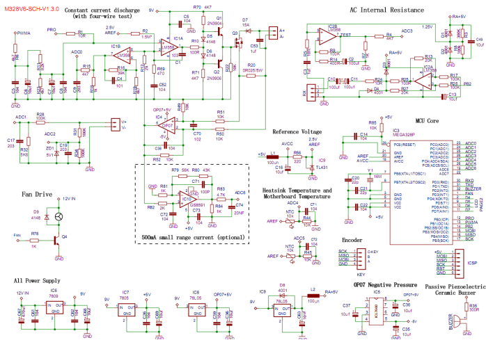
Circuit Diagram:
Circuit Explanation:
· The original design was prone to oscillation and picky with MOSFETs. The new design adds a push-pull MOS driver circuit (Q1/Q2/R70/D5/D6/R71) and a feedback compensation RC network (R69/C52 on the op-amp’s inverting input). C1 is now 103.
· Maximum discharge current is set via the shunt resistor R20:
50 mΩ ≈ 5A, 25 mΩ ≈ 10A, 17 mΩ ≈ 15A (firmware supports up to 15A)
· To reduce heat on the shunt resistor at high current: change R49/R52 to 20K, and configure OP07 for 2× amplification. For 15A range, use R20 = 8 mΩ.
· The circuit inside the "500mA small range current (optional)" box is optional. You can use other rail-to-rail, low-offset single-supply op-amps. This enhances small current accuracy with 0.1mA resolution. Note: ADC6 is only on the SMD version of M328P. If using this, flash firmware that supports ADC6.
· Maximum test voltage is adjusted by the ratio of R28/R32: R32 = 8K2 → 33V, 6K8 → 40V, 5K6 → 47V, 3K9 → 66V (firmware max is 65V)
· R2 provides a bias to LM358’s pin 2 to avoid the MOSFET staying slightly on at no load, and also biases pin 5 to compensate ADC zero offset—improving low-current precision. Adjust R2 via the current calibration menu. Without a load, ensure the ADC shows a small baseline. Adjust R2 accordingly: too low → increase R2; too high → decrease it. A baseline over 64 improves stability but reduces range.
· D7 is a reverse protection diode. Use a high-current Schottky with proper heatsinking. However, this reduces minimum measurable voltage. You may remove it if low-voltage tests are needed, or replace it with a parallel resistor to increase max power capability.
· ZD1 is optional for extra protection.
· R25 sets the AC resistance test range: R25 = 100Ω → 5mA output → 1000 mΩ range; R25 = 50Ω → 10mA output → 500 mΩ range.
· Use a passive buzzer (preferably piezo). If using an electromagnetic type (with coil resistance), drive it with a transistor; MCU IOs can't drive it directly.
· Do not connect CH340 VCC to system VCC. Doing so disables firmware upgrades via serial. CH340 VCC should only connect to the USB port.
· For auto-reset to bootloader on serial upload, connect CH340’s DTR (pin 13) through a 104 capacitor to M328P’s RST. Remove original C14 (RST-to-GND), and pull RST up with 10K. Note: this may cause unwanted resets on some PCs.
· Ensure proper decoupling: place a 104 cap near each chip.
· Use a 16MHz crystal for smoother operation and faster screen refresh. 8MHz crystals are still supported via separate firmware builds.
M328V6 Features
· Compatible with Atmega328P / Atmega644P
· Supports 12864 LCD/OLED (ST7565/ST7567/ST7920/SSD1306)
· Discharge voltage curve display – reduces dependence on PC software
· Voltage/current multi-point calibration (up to 8 points) – corrects non-linearity
· Temperature drift compensation – accurate across seasons
· Constant current / resistance / power modes
· 4-wire and 2-wire testing with wire-loss compensation
· DC and AC internal resistance testing
· Soft current ramp-up – prevents inrush damage
· Adjustable max current (≤15A) and power (≤650W)
· Coulomb meter: Ah (max 999.99Ah) & Wh (max 99999Wh)
· Temperature display, over-temp protection, and auto PWM fan control
· Improved rotary encoder UX
· Scheduled and cyclic load switching
· Four preset voltage/current profiles
· Auto load-on/load-off functions
· USB/Bluetooth serial communication – full control via PC software
Feature Walkthrough
Screen 1: Main Interface
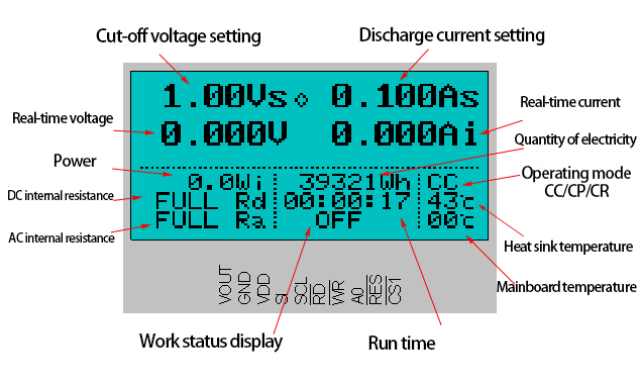
If a horizontal line appears below V/Vi, it indicates that wire loss compensation is currently enabled.
If a flashing horizontal line appears below Ai, it indicates that the MOSFET is in forced fully-on mode.
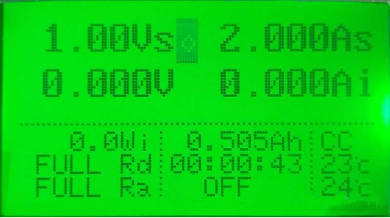
Screen 2: Discharge Voltage Curve
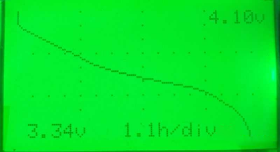
This minimizes reliance on a PC. Although the 12864 screen limits detail, it's enough to observe the discharge plateau. Voltage and time are auto-scaled. The top of the graph is the max discharge voltage; the bottom is the minimum. The curve updates every second, then compresses the timeline to 2s, 4s, etc., as needed.
Screen 3: Large Font Voltmeter/Ammeter
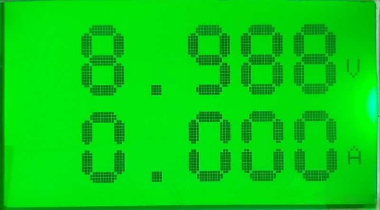
When idle, this screen turns the device into a "bench meter." The large font aids visibility and provides decent precision thanks to multi-point calibration and 512× oversampling.
Warning: In this mode (with no discharge running), long-pressing the center button for 5 seconds enters true ammeter mode, fully turning on the MOSFET. The "A" symbol flashes with an underscore.
In this state, connect the current test leads in series with the load—like a multimeter’s current function. To exit, long-press again or restart. Misusing this mode (e.g., forgetting to switch back before connecting power) can cause sparks and component failure!
Screen 4: Large Font Clock
This screen serves purely as a clock mode, free from any distracting information, and is intended to serve as a desktop timer when the electronic load is idle.
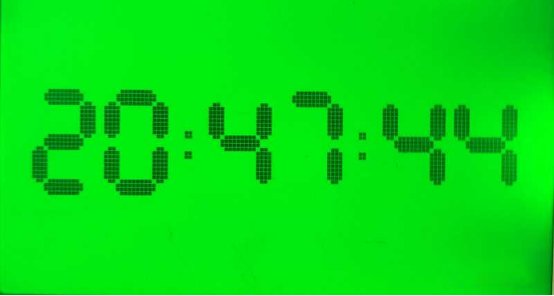
You can synchronize the real-time clock using the PC app. If you enjoy tinkering, you can also connect an external ESP8266 module for Wi-Fi-based time synchronization.
One workaround is to set a scheduled discharge time—for example, 30 minutes. After 30 minutes, the device will automatically begin discharging, but since no voltage source is connected, it will immediately stop and trigger the buzzer, effectively acting as an alarm.
Screen 5: AC Resistance Meter
Placed last for quick access—just turn the encoder right to open it. More convenient for direct AC resistance tests after startup.
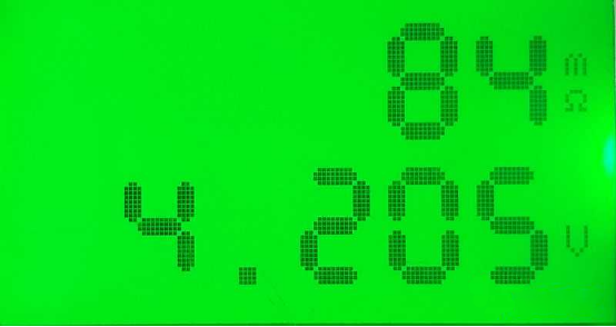
Although the main screen also shows AC resistance, this screen adds convenience with: Large font for visibility; Auto AC module activation when entering this screen, and restoration on exit.
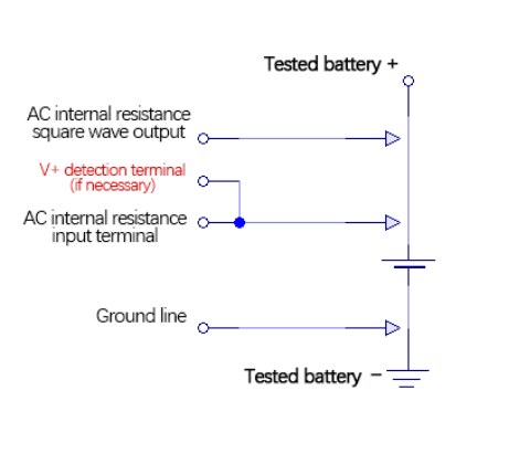
Note: For simultaneous voltage readings, connect only the voltage “V+” terminal to the AC input side (1uF cap C3), and keep the AC output (100uF C10) separate. Else, idle readings may be unstable—but this does not affect real tests with batteries.
Warning: Avoid running AC resistance tests during discharge. Continuous AC current might damage batteries, and disabling it improves efficiency.
Enhanced Button Controls
· In locked mode (diamond icon blinking), rotate left to enter ON/OFF lock mode (ON/OFF blinks at bottom).
· In locked mode, single-click to open the working menu. (No long-press needed anymore) [**1]
· In ON/OFF lock mode, single-click to start/stop discharge.
· Long-press anytime to open the menu (even during voltage/current setting or ON/OFF lock).
· In locked mode, double-click to directly enter current setting mode.[**2]
· In ON/OFF lock mode, double-click to open preset voltage/current menu.
· While in voltage or current setting mode, hold center button + rotate left/right to switch between cutoff voltage and discharge current adjustment.
· Rotate encoder in locked mode to switch display screen (five screens total; main screen has two states).
Note:
**1: From v6.37, click replaced by double click to open the working menu
**2: From v6.37, double click replaced by single click to adjust current
Fuse Bits
Incorrect fuse bits may not affect operation initially but can lead to lost configuration data and frequent recalibration.
With Bootloader
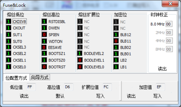
Low: 0xFF
High: 0xD6
Extended: 0xFC
Lock: 0xEF
Without Bootloader
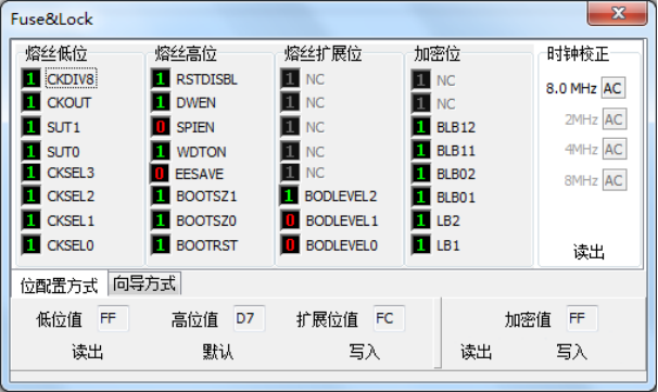
Low: 0xFF
High: 0xD7
Extended: 0xFC
Lock: 0xFF
Done.


