
In previous DIY guides like DIY M8 Electronic Load & Resistance Tester, DIY: Upgrade Your M8 Electronic Load & Tester, and DIY: Upgrade M8V6 Load Tester with Atmega328P, we explored various versions of the M8 constant current digital electronic load and AC internal resistance testers — including the enhanced M8V6 and M328V6 models.
If you're still not satisfied with those versions, this new guide introduces an upgraded version: the M328 G01 Electronic Load. If that sounds interesting, keep reading!
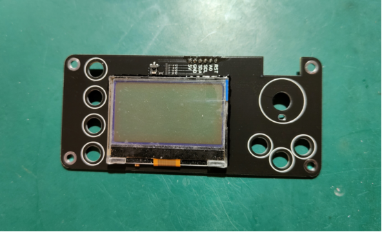
If you're planning a DIY build, you can keep the mainboard unchanged, but the display module must be replaced with a different type of LCD. This will also require modifying the panel cutout to fit the new display.
For the cooling system, design the fan setup based on your actual heatsink. Feel free to modify it as needed. Since the front panel is larger than the mainboard, it can be installed as an embedded module inside the chassis housing.
M328V6 Features:
· Supports 12864 LCD/OLED display
· Discharge voltage curve display to reduce dependency on host PC
· Multi-point calibration for voltage and current (up to 8 points), effectively correcting non-linear behavior
· Temperature drift compensation for consistent accuracy in both summer and winter
· Constant Current / Constant Resistance / Constant Power modes
· Soft-start current ramping to avoid inrush damage to MOSFETs
· Adjustable maximum current and power limits
· Coulomb counter supports Ah and Wh, Ah reading can exceed 65Ah
· Temperature display, over-temp protection, and auto PWM fan — all thresholds adjustable
· Improved rotary encoder control for easier operation
· Supports scheduled load on/off and periodic switching
· Dual communication with PC via USB or Bluetooth serial — full-feature host control supported
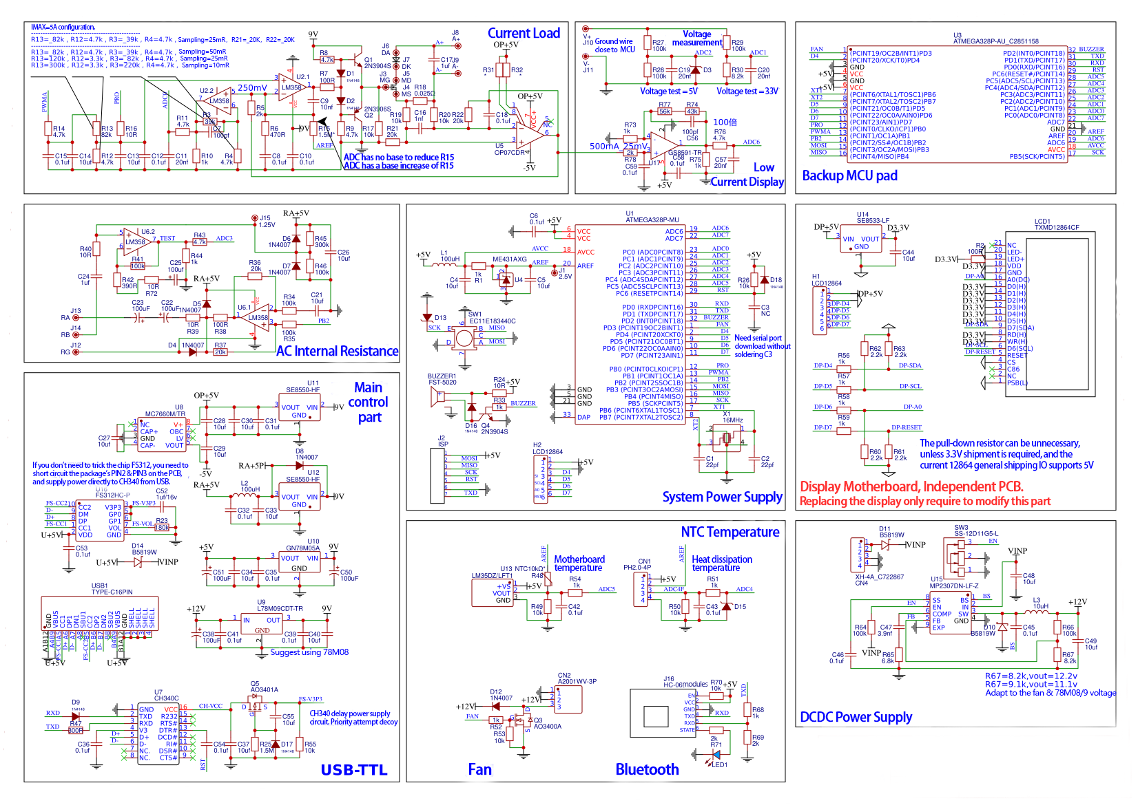
Schematic Diagram:
PCB:
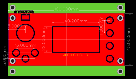
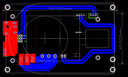
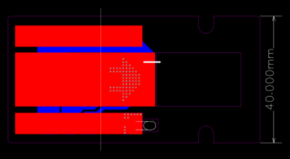
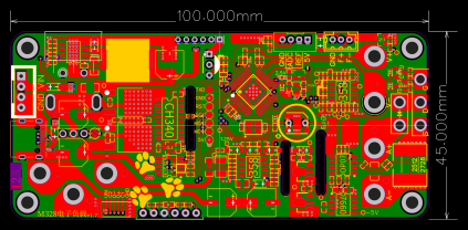
The images below are samples. Circuitry may have minor revisions, but the core functionality remains the same. The front panel is not yet installed. It uses 2mm banana jacks for the interface. You can use a 12V industrial-grade motherboard heatsink.
The heatsink supports up to 60W dissipation. (For data transmission, only DC input is supported.)
The fan has been upgraded from the original 1W to a 4.5W turbine fan.
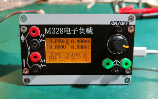
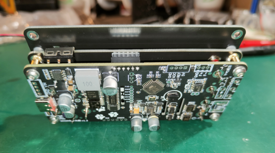
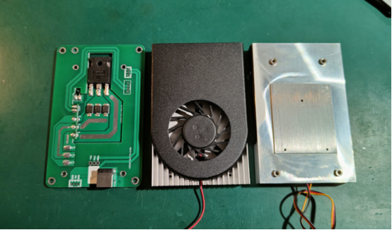
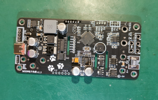
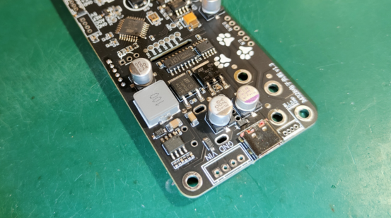
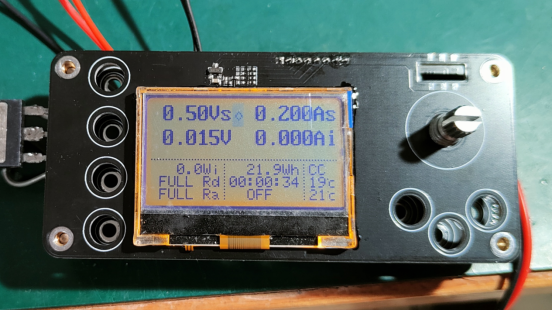
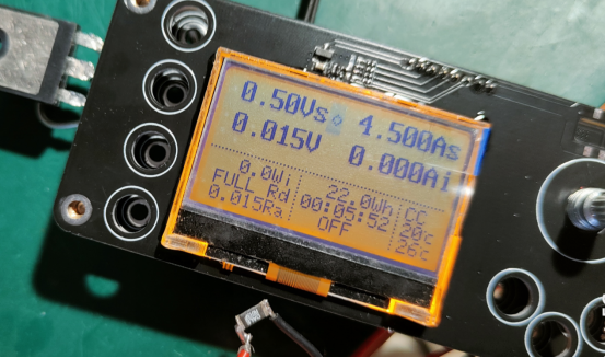
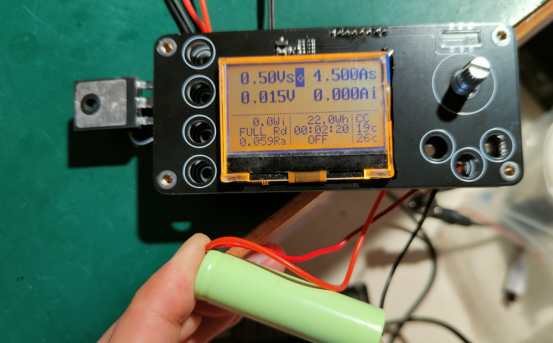
You can also make the following enhancements:
· Update CH340 power supply — Supports QC and PD trigger modes without affecting USB data.
· Revise UART programming circuit — Now supports firmware updates directly via USB serial port.
· Add jumper for op-amp power in load section — Switch between 5V & 9V. Using low-RDS MOSFETs like GS8552/92 enables 5V operation.
· Remove 5V/9V jumper — Default to 9V with LM358 op-amp. Reliable LM358 has typical offset voltage as low as 30µV.
· Add a small current amplifier on back side — Amplifies signals by 100x, with a tentative range of up to 500mA. This is passive display only and does not affect control.
End


